Configuring a custom floor plan for the app
The floor plans displayed in the Planon Workplace app are by default based on multi-layered CAD drawings. If your CAD drawings include many layers and hatched blocks, these floor plans might take quite long to load on the app. They may also lack information that is particularly convenient for app users. In that case, you might consider configuring and linking a customized version of the floor plan.
Planon supports the possibility to combine a CAD drawing with a background image. You can use this feature when creating a custom floor plan for the Planon Workplace app .
Creating an accurate custom floor plan that will only display spaces and workspaces includes the following main steps:
• In AutoCAD, create a simplified version of the relevant CAD drawing. This version can subsequently be used to create an accurate background image. When uploaded as FM drawing, the new, simplified drawing will be combined with the custom background image. See steps 1-3.
• Export the drawing to PDF format; the PDF file is used as the basis for a background image. See steps 4-5.
• Open your preferred drawing tool to edit the floor plan and save the PDF file to PNG format. See steps 6-8.
• Upload the PNG image as CAD background image to Spaces & Workspaces > Floor attributes. See steps 9-11.
• Configure / position the background image in CAD Integrator view. See steps 12-15.
Procedure
1. To define and export the outlines for the drawing, open your floor plan drawing in > .
Decide if the outlines of spaces and desks must be displayed by the FM drawing or by the background image you are about to create. If you keep outlines in both, any misalignment between the background image and the CAD drawing will be quite noticeable. If you want to make the CAD lines invisible in Autodesk, go to Layers and set their transparency to 90. If you want to make the lines invisible in the background drawing, apply the background's transparency when you are editing the background file (see step 7). |
2. Make sure that the layers defining the floor, spaces and workspaces are enabled for printing, by selecting the printer symbol.
This includes layers with information required to draw your background image, the floor polylines, the space polylines, and optionally (if you are going to use them in your background drawing), the workspaces.
3. Disable any irrelevant layers for printing.
4. Select Print to PDF.
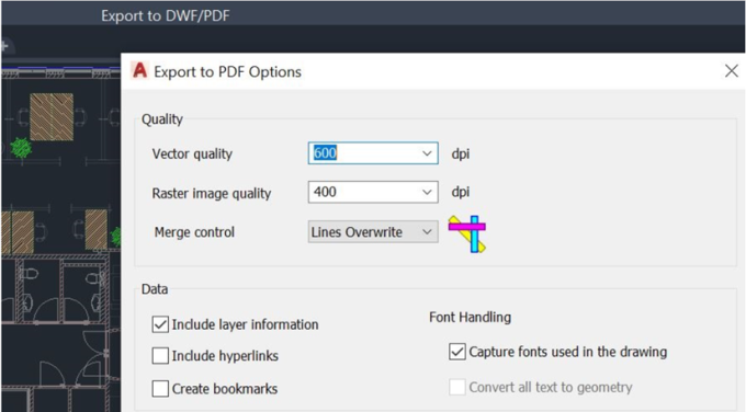
5. Select the following options:

6. Open the PDF file in your preferred drawing tool.
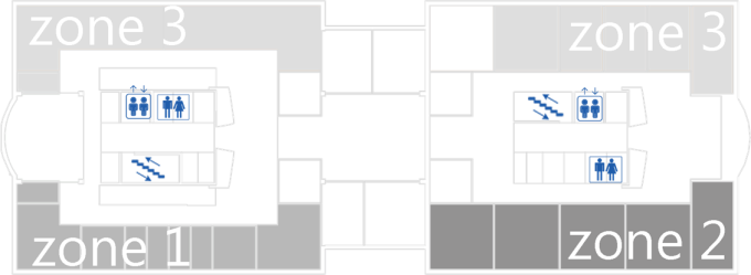
7. Edit the drawing, for example by marking out zones or neighborhoods on the floor plan and making outlines transparent. You might also want to add useful information about the location of lifts, stairs and toilets. See the following example:

It is recommended to only use light colors for your edits, such as grays. You can also use patterns. This ensures that the red and green markers for occupancy remain clearly visible. |
8. Save the file to PNG format.
9. Open Planon ProCenter .
10. Go to Spaces & Workspaces > > .
11. In the CAD background image field, upload the PNG file you just created.
If the field is not displayed, ask your administrator to add it to the Floor attributes layout. Also see Displaying drawings and Floor attribute fields.
12. Go to > .
13. With CAD Integrator view enabled, select the floor that corresponds with the drawing.
14. From the CAD Integrator drop-down menu, select Configure background image.
15. Position the background image as required and select Save background image from the drop-down menu.
The position is saved in the Position field on Floor attributes. The custom floor plan (with configured background image) can now be displayed on the Planon Workplace app .